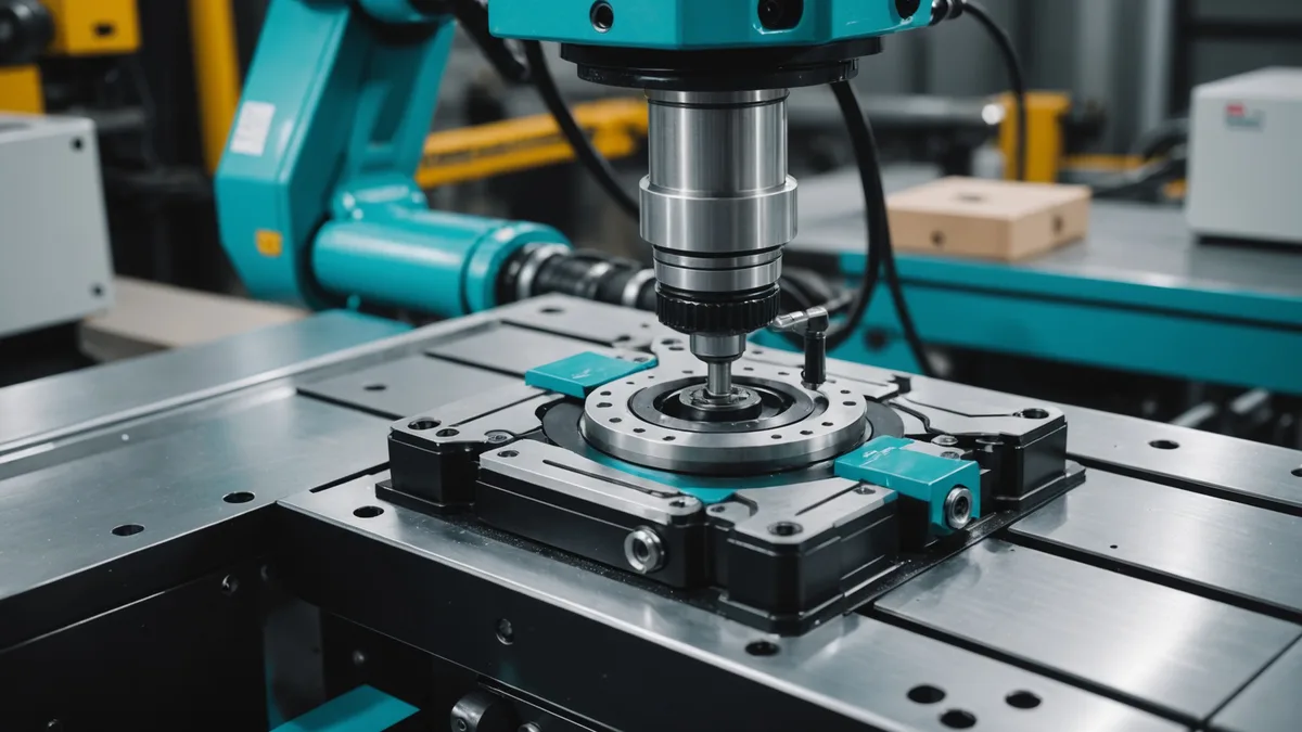
Pick-and-place from a bin is a vision problem. Assembly placement is a contact problem. These are different regimes, and the tools that work well in one often break in the other. A model that produces excellent grasp poses from point clouds can still fail consistently on the final millimeter of a precision insertion, because that final millimeter is governed by the contact geometry between part and fixture, which is occluded from any camera and must be inferred from force and torque signals.
We started treating force-torque (FT) feedback as a separate post-processing module that would override the model's nominal placement trajectory when contact forces exceeded a threshold. That did not work well. The threshold-based approach was too brittle: the right threshold varied by part material, part mass, insertion depth, and fixture compliance, and tuning it for each new part was nearly as much work as the re-teaching it was meant to eliminate.
The approach we have now integrates FT signals directly into the model's action head, treating them as sensory input rather than as an external safety override. This post describes that integration, why it is architecturally different from what most prior work does, and the scenarios where it still fails.
Why FT Feedback Belongs in the Policy, Not Around It
The dominant pattern in industrial robot programming for precision insertion is a separate compliance module: after the robot reaches the nominal placement target pose, a separate impedance controller takes over and uses FT feedback to guide the part into the fixture via small corrective motions. This is a sound engineering approach when you have a fixed part design and can tune the compliance gains and search strategies for that part.
For a foundation model trying to generalize to novel parts, the problem is that the appropriate compliance behavior is part-geometry-dependent. A part with a chamfered lead-in can tolerate larger lateral errors on entry because the chamfer guides it to the correct alignment. A precision slip-fit without a chamfer requires near-zero lateral error before contact. A part with a compressible seal requires force-regulated depth control rather than position control during insertion. None of these are the same compliance strategy, and switching between them requires knowledge of the part's insertion geometry, which the model has from the point cloud.
Embedding FT feedback into the action head allows the model to condition its compliance behavior on the same geometric representation it uses for grasp planning. The action head sees both the current force-torque state and the part's geometry embedding, and its output is a force-regulated Cartesian motion command rather than a pure position target. The model learns, from simulated contact interactions during training, what FT signal patterns correspond to what contact states, and how to respond to them given the part's geometry.
FT Signal Representation and Temporal Context
A wrist FT sensor provides six scalar values: three force components and three torque components, all relative to the sensor frame. At any single instant, these values tell you the current contact state but not much about whether the trajectory is progressing correctly. For insertion tasks, what matters is the trajectory of the FT signal over time: rising lateral force indicates misalignment that is getting worse, a torque spike followed by a drop often indicates the part tip has passed the rim of the fixture opening, a steadily rising axial force with zero lateral force indicates a proper piston-fit insertion in progress.
We encode FT history using a sliding window of the past 20 FT measurements at 200 Hz (100 ms of history) and process it through a lightweight 1D convolutional encoder that produces a fixed-length FT context vector. This context vector is concatenated with the geometric embedding before the action head computes the next motion command. The model can therefore attend jointly to the current part geometry and the recent contact history, which is what allows it to distinguish a chamfer-guided entry (torque rises then drops as part self-aligns) from a jamming event (forces and torques rise without subsequent drop).
The 100 ms window is a deliberate design choice. Longer windows would provide more context but also more latency, and the control loop must respond to contact events quickly enough to prevent damage. For the force thresholds we use on metal parts (typically 30-50 N axial force limit, 2-3 N-m torque limit), a 100 ms response time is adequate.
Simulation Data for FT-Conditioned Training
Collecting real demonstration data for FT-conditioned insertion is expensive: each sample requires a full robot setup with an FT sensor, fixture, and part, and the demonstration must be performed at high enough control frequency to capture the contact dynamics. We generate training data primarily through simulation, using PyBullet with its contact dynamics, supplemented with a small number of real demonstrations to calibrate the sim-to-real gap in the FT signals.
Sim-to-real transfer for FT feedback is harder than for vision. The contact physics in simulation, particularly the stiffness and damping of contact constraints, does not match real metal-on-metal contact well. The specific failure mode is that simulation tends to produce smoother, more predictable FT trajectories than real hardware, because simulated contact stiffness is finite and constant while real mechanical contacts have micro-geometry and stick-slip behavior that creates high-frequency noise and transient spikes.
We handle this in two ways. First, we add synthetic noise to the simulated FT signals during training: Gaussian noise at a magnitude calibrated to match the noise floor of our physical FT sensor (an ATI Mini45), plus occasional synthetic spike events that simulate contact transients. Second, we train with domain randomization on the contact stiffness parameters in PyBullet, which forces the model to generalize across a range of contact dynamics rather than overfitting to a specific simulated contact model.
A Realistic Test Case: Shaft-into-Bushing Insertion
We tested this approach on shaft-into-bushing insertion with a 0.05 mm bilateral tolerance (H7/f6 fit). The shaft is a turned steel cylinder, 18 mm diameter, 45 mm long, inserted vertically into a bronze bushing press-fitted into an aluminum fixture block. The insertion requires better than 0.1 mm lateral alignment at contact to avoid jamming.
Our point cloud-based pose estimation produces lateral alignment errors in the range of 0.2-0.4 mm at the bushing opening, which is insufficient for reliable contact entry on its own. Without FT feedback, the insertion fail rate was above 40%. With the FT-conditioned action head, the system corrects the lateral position during the entry phase using the torque feedback as an alignment signal, and the insertion success rate rose to around 85% on this specific task over 60 trials.
We want to be clear about what that number means. The 85% figure is on one specific part geometry and fixture with a consistent ambient temperature and the FT sensor calibrated the same morning. In a production setting with temperature drift, varying part surface finish, and occasional contamination on the shaft or bore surfaces, we would expect the number to be lower. We present it as a directional indicator, not a production specification.
Where the Approach Breaks Down
The FT-conditioned action head relies on the model having seen relevant contact dynamics for the part geometry during training. If a part geometry is far outside the training distribution in a way that produces novel contact signatures, the model's FT interpretation can be wrong. We saw this with a snap-fit connector whose locking tabs created a characteristic double-force-peak during insertion that the model had not encountered and misclassified as a jam event, causing it to retract when it should have continued.
High-frequency vibration from nearby machinery couples into the FT sensor and is difficult to distinguish from contact events at the frequencies relevant for compliance control. We use a low-pass filter at 50 Hz on the FT signal, which attenuates most machinery vibration but at the cost of slower response to genuine contact transients.
FT sensors add cost and complexity to the end-effector that some factory setups will not accommodate. An ATI Mini45 costs several thousand USD and requires careful wrist integration. For low-tolerance placements where vision-based pose accuracy is sufficient, the FT integration is unnecessary overhead. We are clear with users that FT feedback is relevant for tight-tolerance insertion tasks, not for general bin picking where the placement tolerance is loose.