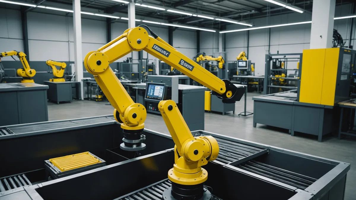
We had been running our model in simulation and on a research UR5 setup for months before our first FANUC deployment. The move to FANUC hardware was not primarily a technical leap, it was a context shift. FANUC cells run FANUC's own controller software (R-30iB), communicate via dedicated fieldbus protocols, and have their own conventions around coordinate frames, TCP definitions, and safety zone configuration that bear no resemblance to how academic robotics stacks work. Getting a grasp prediction from our model into a commanded joint motion required integrating with all of that.
This post is the notes we wish had existed before we started. It covers the integration path we took, the calibration procedure we ended up with, the sensor mounting decisions and why they matter, and the specific failure modes we hit on FANUC hardware that we had not seen on our research setup.
The FANUC Controller Communication Path
FANUC's R-30iB controller does not expose a modern robot description or planning interface. External systems communicate with it through Karel programs, the controller's own macro language, or via FANUC's robot server options (DCS, iRVision, ROBOGUIDE server) if they are licensed. Most production cells that automation shops have built use Karel for custom motion sequences and access external position registers through structured data transfers over PROFINET or Ethernet/IP.
We chose to implement a thin ROS 2 bridge that writes computed grasp poses into FANUC position registers via a FANUC Ethernet/IP driver, and a corresponding Karel program on the controller side that polls those registers, validates the incoming pose against a predefined safe workspace envelope, and executes the approach-grasp-retract sequence. The motion planning itself stays on the controller side, where FANUC's joint interpolation handles the actual path execution. Our model is responsible only for the grasp pose target, not the motion trajectory.
This boundary is important for safety certification. If our system runs entirely outside the FANUC controller, the controller's built-in safety monitoring still runs independently, and any overspeed or workspace violation triggers an emergency stop regardless of what our code says. We treat this as a feature, not a constraint.
Calibration: Hand-Eye and More
Hand-eye calibration for a fixed-mount camera above a robot cell is well-understood in principle, but the implementation details matter more than the algorithm. We used a calibration procedure based on a printed dot pattern affixed to a calibration plate that we can attach to the FANUC's flange. The robot moves the plate to 15-20 poses spanning its workspace, and we solve for the camera-to-robot-base transform using a standard AX=XB formulation.
On our research UR5, this was straightforward. On the FANUC LR Mate, we ran into two issues. First, the FANUC tool center point (TCP) definition must exactly match the physical geometry of whatever is attached to the flange, and the default TCP in our test cell had been set by a previous programmer for a different tool. We did not notice this immediately. The calibration appeared to solve correctly, but the resulting pose estimates were offset by 4-6 mm in the Z direction, which is enough to cause grasp failures on small parts. The fix was trivial once we found it: measure the actual TCP geometry and redefine it in the FANUC system configuration before running calibration.
Second, the structured-light sensor we used initially (a Photoneo Phoxi S) has a non-negligible warm-up period during which its projector temperature affects the projection pattern geometry and therefore the depth accuracy. We were doing calibration in the morning when the lab was cold and running trials in the afternoon after the sensor had stabilized thermally. The effective calibration error between these two states was about 1.5 mm on a 600 mm field, which sounds small but is significant for assembly placement. We now include a 20-minute sensor warm-up before calibration and again before any precision trial.
Sensor Mounting: Height, Angle, and Illumination Interaction
We originally mounted the camera directly overhead at about 750 mm above the bin floor. This gave us maximum field of view over the bin and minimized the oblique-angle missing-data problem on the sides of parts. But it also created a problem specific to parts with flat horizontal faces: structured-light sensors illuminating a flat surface from directly above return very high signal-to-noise ratio depth data for that surface but poor data for vertical faces and recessed features, because the structured-light pattern reflects directly back from the horizontal face and scatters from the vertical faces.
We moved the sensor to 680 mm at a 15-degree forward tilt. The slight angle changes the illumination geometry enough that we get usable data from both horizontal and near-vertical surfaces on most parts, at the cost of some increase in missing-data area near the far bin wall. For our target part height range (15-80 mm tall), this is the better tradeoff.
Ambient factory lighting also matters more than we expected. The test cell had four overhead fluorescent fixtures, and on overcast days when the natural light from the facility's skylights was lower, the fluorescent contribution to the infrared band was lower than on bright days. This created a systematic difference in the structured-light signal quality between high-ambient and low-ambient conditions. We ended up adding a diffusing light baffle above the sensor to reduce ambient IR variability, which stabilized the depth map quality across lighting conditions.
Latency Budget and the Grasp Replanning Question
Our model running on a compact inference board (NVIDIA Orin NX module) takes 95-110 ms to process a point cloud and return a grasp pose distribution. The Ethernet/IP register write from our ROS 2 node to the FANUC controller takes 5-15 ms depending on the polling cycle. The Karel program on the controller side checks the register every 8 ms. So from point cloud capture to motion start, the minimum latency is about 120-135 ms, and in practice we see 140-180 ms including the point cloud acquisition time for the Phoxi sensor.
This latency is acceptable for static or near-static bin configurations, where the parts do not move between the vision cycle and the grasp execution. It is not acceptable for high-speed conveyor applications or for bins with vibration from adjacent machinery that causes parts to shift during the grasp approach. We are clear with users considering those contexts: the current system is designed for parts in a stationary bin or part fixture, not for grasping from moving lines.
Grasp replanning, where the system takes a second look if the first grasp fails, adds another 140-180 ms cycle. The FANUC controller's Karel program can trigger a replan request via a register flag if the part was not detected in the gripper sensor after a grasp attempt. In our testing, two-attempt grasp success rates were meaningfully higher than single-attempt rates for parts with shape ambiguity or bin-edge placement, and the added cycle time was acceptable for the target application.
Failure Modes Specific to This Setup
Three failures we observed were specific to the FANUC integration and would not have shown up in our lab testing.
Register overflow: the FANUC position register format stores coordinates as 32-bit floats. Our pose representation uses 64-bit doubles internally. Converting to 32-bit on write introduced rounding that accumulated in the rotation component of the pose to an error of about 0.15 degrees. This is small but enough to matter for precision placement tasks. We now explicitly round the rotation representation to 32-bit precision in our ROS 2 node before the register write, and verify the round-trip by reading back the register value immediately after writing.
Karel program timeout: the Karel polling program has a built-in watchdog that triggers an alarm if it does not receive a new register value within a configurable interval. We set this initially at 500 ms, which was fine in the lab but insufficient when our inference board occasionally took longer due to thermal throttling. Setting it to 1200 ms and adding a health check endpoint to the inference board resolved this.
Workspace validation mismatch: the safe workspace envelope defined in the Karel program did not match the actual reach envelope of the FANUC LR Mate 200iD/7L we were using. Some valid grasp poses near the bin edges were being rejected by the Karel safety check and silently dropping the grasp request. The solution was to use ROBOGUIDE to visualize the exact reachable workspace and redefine the envelope accordingly.
None of these failures were fundamental. They were integration details, the kind that add up to several weeks of debugging time when you are learning a new controller platform. We are documenting them here because they are unlikely to appear in any academic paper but very likely to cost you time on your first FANUC deployment.